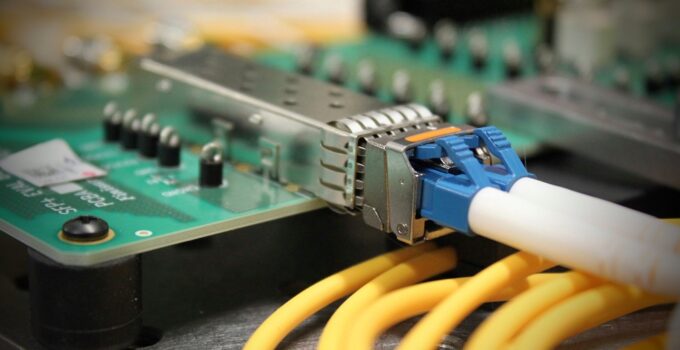
In the 10 Gbit/s network transmission, SFP+ modules have become the main force in the market due to their low cost, small size, and large transmission capacity. This paper takes SFP+ optical modules as an example, using a four-channel test platform way to test. First of all, the direct data input and output between the PC host computer and the lower controller is guaranteed through the circuit design, and the design scheme of voltage conversion is proposed to adapt to the standard module. Secondly, use the least-squares method to linearly fit the optical power and the bit error rate to obtain the process of module sensitivity, and judge whether there is noise interference by observing the eye diagram waveform. Finally, in terms of test data, the improved method supports a variety of adjustable test rates, and the test results remain stable at both high and low temperatures and normal temperatures, which proves its good effect.
As the core device in the optical fiber communication system, the optical module is of great significance, and how to test the performance of the optical module quickly and accurately is a key link. Therefore, the design and optimization process of a 10 Gbit/s SFP+ optical module (click here) test platform is introduced. Firstly, it focuses on analyzing the design steps of a multi-channel test board, including the design method of USB to I 2 C and power supply; and then discusses the principle of using the SFF-8472 protocol as a standard to calibrate and monitor important data with digital diagnostic functions. Finally, the module is tested, and the results show that the system bit error rate is below 1E-13, and the error between the optical power and the standard value is stable at ± 0. 5 dBm, which shows the feasibility of the proposed multi-channel test and proves that it can improve the test efficiency.
System Structure of the Test Platform
Source: fiber-optic-tutorial.com
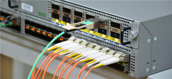
The optical module test platform is mainly composed of BERT, optical attenuator, multi-channel system communication board, test board, and eye pattern meter. The 1310Tx/1510Rx receiver module is selected for testing. The test board is connected to the computer by means of parallel port simulation, which is mainly used to realize electro-optical conversion, and the test board and the tested module are controlled by the I 2 C bus. The normal communication between the BERT and the computer is carried out through the RS232 interface or the USB interface as a medium. At the transmitting end, multi-mode optical switches and optical attenuators are used, combined with wavelength division multiplexers, to complete the simultaneous transmission of light of different wavelengths. As the main control device of the test, the computer must take into account the processing of data and the coordinated use of the instrument. Its specific function is to send instructions through the parallel port to simulate I 2 C to complete the data acquisition required for digital diagnosis, so as to further analyze the data. and adjustment. Finally, use the GPIB controller to analyze the operation of the eye pattern instrument and read the data to obtain the eye pattern information.
Multi-Channel Test Board Design
Source: androidpimp.com
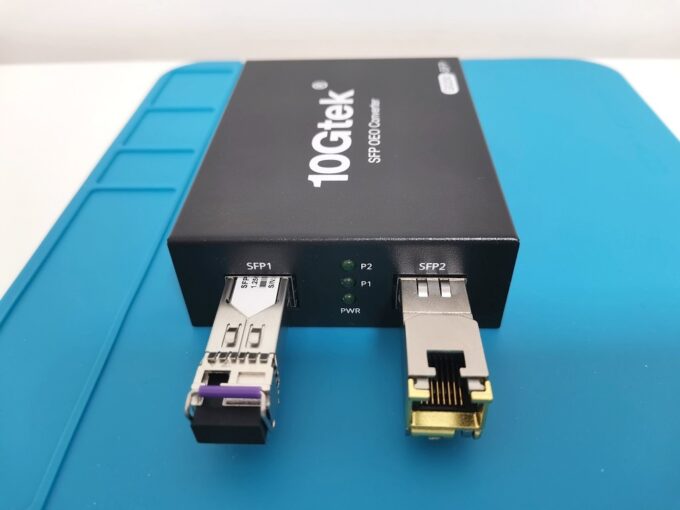
I 2 C (Inter-Integrated Circuit) is the name for the internal integrated circuit, and it is also a serial communication bus. The I 2 C protocol is a two-wire interface, that is, information is transmitted between the serial data (Serial Data, SDA) and serial clock (Serial Clock, SCL) lines and the devices on the bus. The specific method is that when SCL is at a high level, SDA transitions from high level to low level, and data transmission starts from this, and when SCL is at a high level and SDA transitions from low level to a high level, data transmission ends.
The standard operating voltage of SFP+ optical modules is about 3. 3 V, the working current is about 200 mA, convert the 12 V to 3. The 3V power supply is used as a standard module, so this power supply design adopts a step-down switching power supply, which can convert the 12V input voltage into 3. 3 V output voltage. An integrated power controller (SC4519) is also used on this power supply, which has independent synchronization and enables functions to support low-cost and low-power solutions, and this controller integrates the power transistor inside the chip, simplifying the power supply design process.
Optical Transceiver Module Performance Test
Source: servethehome.com
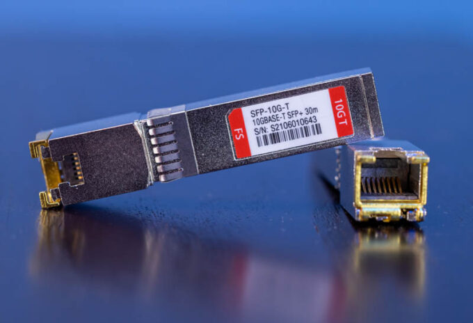
The test items mainly include the effect of sensitivity, bit error rate, optical power, and eye diagram. The main principle of the test is that the internal module of the BERT generates a pseudo-random code sequence, and transmits it to the module under test using the external interface of the monitoring system. At the same time, the signal will be shunted to the receiving end of the optical module through the optical attenuator, and the receiving interface will complete the photoelectric conversion and deliver it to the error detection module; then, the received error sequence is compared with the initial random sequence, so as to obtain the error code rate.
Conclusion
With the continuous development of communication technology and the continuous improvement of network transmission capacity, optical fiber communication has become one of the main communication methods at present. As the core device in the optical communication network, the optical module can not be underestimated. It is often used as the carrier for transmission between switches and devices. Compared with the general transceiver, its efficiency and security can be better. guarantee. But today, the types and rates of optical modules are increasingly updated, and the testing process has also become complicated. Therefore, it is necessary to improve the test method of optical modules to further improve the test efficiency.


